Knowing how to install a motherboard calmly and in the right order is what separates a smooth first boot from an afternoon of troubleshooting. The job itself is not difficult — the board is secured by a handful of screws and everything plugs into keyed connectors that only fit one way — but it rewards patience and sequence. Some parts are far easier to fit before the board goes into the case, and some cables are nearly impossible to reach afterwards. This guide follows the order experienced builders use, from preparing the case to the moment you are ready for a first power-on test.
Two safety habits run through every step. First, work with the power supply switched off and unplugged whenever your hands are inside the case; the board should never be handled or reseated while the system is connected to power. Second, protect the board from static: touch a grounded metal object before handling it, work on a non-carpeted surface where you can, and hold the board by its edges rather than across its components. None of this needs special equipment — just deliberate habits.
Disclosure: As an Amazon Associate, ilcastellomenu.com earns from qualifying purchases. Product links on this page may earn us a commission at no extra cost to you, and that support helps us keep testing and writing guides like this one.
How to Install a Motherboard: What You Need Before You Start
Gather everything first so the build never stalls half-assembled. You will need a Phillips screwdriver (a magnetic tip helps enormously with dropped screws), the case’s accessory box with standoffs and screws, the motherboard’s manual — keep it open, because header layouts differ by model — cable ties for tidying, and good light. A small tray or magnetic dish for screws prevents the classic lost-screw-under-the-board problem, which matters because a loose screw behind a powered board can short it.
- Phillips screwdriver, ideally magnetic, plus the case accessory screws and standoffs
- Motherboard manual, printed or open on a second screen
- Anti-static habit: grounded metal to touch, non-carpeted work surface
- Cable ties or hook-and-loop straps for final cable management
- A small container for screws, and a flashlight for dark case corners
In this guide
Step 1: Prepare the Case and Fit the Standoffs
Start with the empty case. Remove both side panels and lay the case on its side on your work surface so gravity helps rather than fights you. Find the standoff positions: these are the small brass pegs the board screws into, and they must match the mounting holes of your board’s form factor exactly. Cases often come with standoffs pre-fitted for full ATX; if you are installing a smaller board, some may need moving. Compare against the board itself — hold it above the tray and confirm every mounting hole has a standoff beneath it, and that no extra standoff sits where the board has no hole. An extra standoff touching the back of the board is a short circuit waiting for power.
Fit the I/O shield next, if your board uses a separate one. It snaps into the rectangular cutout at the rear of the case from the inside, with the printed labels facing out, and it needs firm, even pressure on all four corners until it clicks. Many newer boards have the shield pre-attached, which removes the single most-forgotten step in PC building — discovering the shield after everything is cabled means taking it all apart again. If you are still choosing a case for the build, the options in Best PC Cases for Under 100 cover the mainstream sizes this step depends on.
Step 2: Fit the CPU, Cooler Mounting, and Memory on the Bench
The board is much easier to work on outside the case, so install the processor now. Lift the socket’s retention arm, align the CPU using the corner markers printed on both chip and socket, lower it into place without any force — a correctly oriented CPU settles in under its own weight — and close the arm. If anything resists, stop and re-check orientation; a forced CPU bends pins and ruins both parts. Fit the cooler’s backplate and mounting hardware at this stage too, since several designs attach from behind the board, which is awkward or impossible once the board is mounted.
Install memory next. Open the slot clips, align the notch in each stick with the key in the slot, and press down firmly with both thumbs until the clips snap shut. For a two-stick kit, use the pair of slots your manual recommends — usually the second and fourth slots from the CPU — because that pairing is what enables dual-channel operation at full rated speed. If your build is still at the planning stage, How to Choose a Motherboard covers how these parts were matched in the first place, and How to Check Compatibility of a Motherboard shows how to verify them before you buy.
Step 3: Fit M.2 Storage While the Board Is Accessible
M.2 drives mount flat against the board under small screws or tool-free latches, and the primary slot often hides beneath a heatsink or, later, beneath the graphics card. Installing your NVMe drive now takes thirty seconds; installing it after the GPU is fitted can mean removing the card. Seat the drive at a shallow angle into the slot, press it flat, and secure it — snugly, not forcefully, as the tiny screw strips easily. If the slot has a heatsink, peel the protective film from its thermal pad before refitting it, a detail that is easy to miss and quietly ruins the heatsink’s contact.
Step 4: Lower the Board Into the Case
With the case lying on its side, lower the board in at a slight angle, guiding the rear ports through the I/O shield first. Watch for the shield’s thin grounding tabs: they should rest on top of the port housings, never bent inside a USB or network port, where they can block a plug or cause a short. Once the ports sit flush in the shield, settle the board flat so every mounting hole lines up over its standoff. If a hole does not line up, do not flex the board toward it — lift the board out and correct the standoff pattern instead.
Start all the screws before tightening any of them, working in a loose cross pattern, and finish each one snug rather than cranked. The board should feel solidly held with zero flex when you press gently near a corner. Overtightening cracks solder joints and warps the board; undertightening leaves it free to shift when heavy cables are plugged in.
Step 5: Connect Case Front-Panel Wires and Storage
The front-panel header is the fiddliest part of the whole installation: a row of small pins carrying the power switch, reset switch, power LED, and drive activity LED. Your manual has the pin diagram — follow it exactly. The switches do not care about polarity, but the LEDs do, so if a light does not work afterwards, reversing its plug is the fix, not a fault. Take your time here and use the flashlight; guessing at this header is how builds end up with a reset button that powers the machine off.
Connect SATA data cables to any 2.5-inch or hard drives now, while the board’s edge is still reachable, and route them through the nearest case grommet. Front-panel USB and audio headers are keyed and only fit one way — align them, press firmly, and never force a connector that resists, because bent header pins are miserable to straighten.
Step 6: Fit the Power Supply Connections
Two power cables feed the board. The wide 24-pin main connector goes to the board’s right edge and clicks home with a latch; it needs a firm, straight push and should sit with no gap. The CPU power cable — a 4-pin, 8-pin, or paired connector depending on the board — plugs in at the top-left corner near the processor, and it is the one most often forgotten, producing a build that lights up but shows nothing. Route it behind the motherboard tray before the board went in, if your case allows, because that corner becomes very tight once a large air cooler is fitted.
A note on cable identity: the CPU power cable and the graphics-card power cable can look similar but are keyed differently and are not interchangeable. Check the labels moulded on the connectors rather than forcing a fit. Only after every connector is seated should the graphics card go in — it locks into the top PCIe slot with a click, gets screwed to the case bracket, and takes its own power cables last.
Step 7: The First Power-On Check
Before closing the case, do a first boot with the side panel off. Reconnect the power supply cable, switch it on, and press the case power button. You are looking for fans spinning, any diagnostic LEDs on the board stepping through their sequence, and an image on the monitor — which must be plugged into the graphics card, not the motherboard, on systems with a dedicated GPU. A first boot can take longer than you expect, especially on newer platforms where the board trains its memory settings; give it a full minute or two before concluding anything is wrong.
If the machine does not start, stay calm and work the simple list: power supply switch on, CPU power cable seated, front-panel power switch on the correct pins, memory fully clicked in. Those four account for the overwhelming majority of no-start builds. For a systematic walk-through when a board shows no sign of life, keep How to Fix a Motherboard that Will Not Post open — it orders the checks safely from least to most invasive. When everything works, power down, unplug, tidy the cables away from fan paths with your ties, refit the panels, and only then set the machine up at its desk.
Common Installation Mistakes to Avoid
The hall of fame: forgetting the I/O shield until after cabling; a stray standoff shorting the back of the board; memory in the wrong slots, quietly halving memory performance; the CPU power cable left unplugged; the monitor plugged into the motherboard on a system whose CPU has no integrated graphics; and the protective film left on an M.2 heatsink. Every one of these is a five-second check during the build and a frustrating teardown afterwards, which is why this guide front-loads them.
The other mistake is rushing the finish — closing the case before the first boot test. Testing with the panel off turns a fault into a two-minute cable check instead of a full disassembly. Experienced builders treat the open-case first boot as part of the installation, not an optional extra.
Installing the CPU Cooler: the Part Everyone Asks About
The cooler deserves its own moment because it interacts with the board installation at three points. First, mounting hardware: many coolers bolt through the board to a backplate, and fitting that backplate after the board is in the case ranges from awkward to impossible, which is why this guide fits mounting hardware on the bench. Second, orientation: an air cooler’s fan should blow toward the rear exhaust of the case, and its body must clear the memory slots and the top expansion slot — check both before the board goes in, because rotating a cooler 180 degrees after the fact means re-doing its thermal paste too. Third, the fan cable: it belongs on the header labelled CPU_FAN, and routing it before the board is mounted keeps it out of the fan’s own blades.
Thermal paste, briefly: if your cooler does not come with it pre-applied, a pea-sized amount centred on the CPU is the standard method, and the cooler’s pressure spreads it. More is not better — excess squeezes out and makes a mess without improving contact. If you remove a cooler after it has been seated, clean both surfaces and apply fresh paste; reusing compressed paste traps air and costs cooling performance you will chase as a mystery temperature problem later.
Liquid coolers add one routing note: the radiator and its fans mount to the case, the pump block to the CPU, and the pump’s cable to a pump or CPU fan header as the manual directs. Fit the radiator before the board if the case is tight, and plan tube routing so nothing presses on memory or the graphics card.
Cable Routing That Your Future Self Will Thank You For
Route cables behind the motherboard tray wherever the case allows, bringing each one through the grommet nearest its connector. The 24-pin power cable and the graphics-card cables are the bulky ones; the CPU power cable is the one to route first, before the board goes in, because its connector sits in the case’s most crowded corner. Keep cables out of fan blades and away from the paths your hands will take when you inevitably add a drive or swap memory later — because you will, and the machine you are building today is the machine you will be upgrading in two years.
Do not strangle cables with ties before the first successful boot. Build it loose, test it, and only then tidy. The classic rookie sequence — perfect cable management, closed panels, no boot, full teardown — exists because tidiness was prioritised over testability. Zip ties are cheap; cut them without sentimentality whenever they stand between you and a connector.
After the First Boot: Ten Minutes of Setup That Matter
A successful first boot is the halfway point, not the finish. Enter the BIOS and confirm the basics while everything is fresh in your mind: all memory recognised and running in dual channel; the memory profile (XMP or EXPO) enabled so the kit runs at its rated speed; every drive visible; fan curves set to something sane rather than full-speed defaults; and the boot order pointing at your installation media or your system drive. Check the CPU temperature at idle while you are there — it should sit comfortably low; a high idle temperature found now is a cooler-mounting fix, found later it is a mystery.
Then install the operating system, and after that, the chipset and device drivers from the board manufacturer’s support page — these are more current and more specific than whatever the OS installs generically, particularly for networking and audio. Only once the machine is fully working should the panels go on for good and the cable ties come out. Installation, done in this order, ends with a machine you understand, because you verified it layer by layer as you built it.
Fitting the Graphics Card and Final Connections
With the board powered and cabled, the graphics card is usually the last major component. Before fitting it, remove the correct expansion-slot covers from the case — count from the slot the card will occupy, because removing the wrong cover is a rite of passage nobody enjoys repeating. Open the slot’s retention latch, align the card, and press it home with even pressure until the latch clicks; the card should sit level, fully seated along the whole slot, with its bracket flush to the case. Secure it with screws — a heavy card held only by its slot will sag and stress the connector — and consider a support bracket for the largest cards. Then connect its power cables from the power supply, using separate cable runs for cards with multiple connectors where the supply allows, as the supply’s manual directs.
Finish the remaining connections methodically, manual in hand: case fans to their headers, any lighting connectors, the storage drives’ power cables from the supply, and a final check of the front-panel block. Then perform the fingertip audit — every connector in the build gets one gentle push to confirm it is fully home: 24-pin, CPU power, memory (visual clip check), graphics power, SATA at both ends, fan headers. This two-minute ritual catches the connector that was 90 percent seated, which is the single most common cause of ‘built it perfectly, will not start’. Only now does the build earn its first power-on, with the panels still off and your troubleshooting guide within reach.
Gear for This Guide
The products below come from our verified listings pool and are mentioned because they genuinely fit this topic, not because they are the newest or the most expensive option.
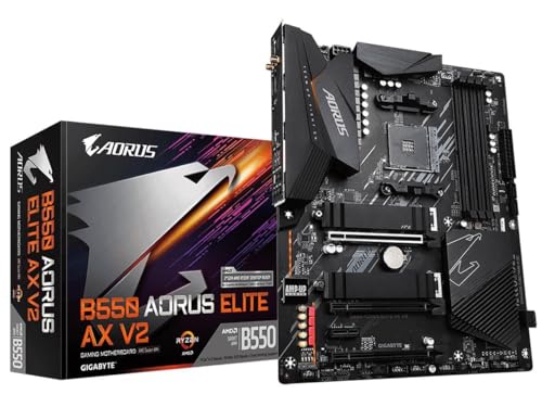
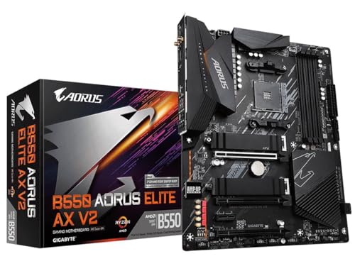
- GIGABYTE B550 AORUS Elite AX V2 AMD AM4 ATX Motherboard, Supports Ryzen 5000/4000/3000 Processors, DDR4, 12+2 Power Phase, 2X M.2, PCIe 4.0, Front USB-C, WIFI6, 2.5 GbE LAN, Q-Flash Plus, RGB Fusion — an ATX board whose CPU-less BIOS flash feature is genuinely useful during installation: if the fitted processor needs a newer BIOS, you can update it without first hunting down a supported CPU. Check on Amazon
Before the First Screw: The Bench Test That Saves Afternoons
Professional builders often perform one step this guide’s main sequence omits, because for a first-timer it can look intimidating: they test the core components outside the case before installing anything. Place the motherboard on its box — the cardboard is non-conductive and slightly padded — fit the CPU, cooler, and one memory stick, connect the power supply’s 24-pin and CPU power cables, and start the board by briefly bridging the two power-switch pins on the front-panel header with a screwdriver tip. A display connected to the graphics card (or the board’s video output, if your CPU has integrated graphics) should show the BIOS screen within a minute, after the memory training pause described earlier in this guide.
The value of the bench test is isolation. Inside a case, a failure to start has a dozen possible causes tangled together: standoffs, front-panel wiring, a short against the tray, cables you cannot see. On the box, the list collapses to the core parts themselves. If the bench test passes, every later problem is an installation problem, and you will hunt it with the confidence of someone who knows the parts are good. If it fails, you have found out while the components are still easy to remove, reseat, and — if it comes to it — return. Twenty unhurried minutes here routinely saves an hour of case-open diagnosis later. The cautions are simple: never run the board on the anti-static bag it shipped in, because the bag’s outer surface is designed to conduct charge away and is not an insulating work mat; keep the running time short and the cooler properly fitted, since the CPU needs its cooling even for a BIOS check; and power everything down before moving parts between the bench and the case.
Timing and difficulty, stated plainly for the whole job: a first installation, bench test included, typically takes between one and two hours at a calm pace, and experienced builders do the same work in half that. Almost none of the time is spent turning screws. It goes on reading the manual’s diagrams, routing cables through the right grommets before connectors make routing impossible, and double-checking the front-panel header. Budget your time accordingly — start when you have an unhurried block, not late in the evening — and treat any urge to force a connector as a stop signal. In a correct installation, nothing needs force beyond firm, straight pressure on the large power connectors and memory sticks.
How the Job Changes With the Build: Three Scenarios
The compact case: Mini-ITX and small form factors
Small cases reverse several of this guide’s default assumptions. Access is so tight that the order of operations stops being a preference and becomes the only order that physically works: cables often must be routed and even plugged in before the board is fully seated, because the power supply or a drive cage will block the connectors afterwards. The power supply itself may mount in front of or above the board, and its cables are short by design, which punishes improvisation. Work even more slowly than usual, photograph the interior before closing panels you will struggle to reopen, and expect the front-panel header — always small — to be genuinely awkward rather than merely fiddly. The compensation is that a finished small build has almost no wasted motion in it; every cable you placed deliberately stays placed.
The transplant: moving a working board to a new case
Re-casing an existing, working system is the friendliest variation, because every part is a known quantity. The work is removal in reverse order of installation: photograph the cable layout before unplugging anything, label the front-panel wires if the case is changing (the new case’s wires may be labelled differently), and keep the CPU, cooler, and memory installed on the board throughout — there is no reason to disturb working connections. Two traps recur. The standoff pattern belongs to the new case, not the old one, so check it afresh rather than assuming; and the old case may surrender its I/O shield reluctantly or not at all, so confirm the shield transfers or that a replacement is at hand before the board is homeless. Because the parts already work together, skip the bench test, but keep the panel-off first boot in the new case.
The replacement: a new board in an existing system
Swapping a failed or outdated board while keeping the case, drives, and other parts adds a software dimension the mechanical steps do not hint at. Back up anything irreplaceable before you begin, even though the drives are not being touched — you are about to change the component every other part talks through. Record your old BIOS settings if the old board still runs, particularly boot order and any storage controller mode, because a mismatch in that one storage setting is the classic reason a transplanted system refuses to load its operating system. After the swap, expect the operating system to spend its first boot detecting new hardware, and plan to install the new board’s chipset, network, and audio drivers from the manufacturer’s page, removing the old board’s equivalents if the system behaves oddly. If the new board uses a different CPU socket or memory generation, of course, the job is no longer a replacement but a platform change, and the compatibility checks in our motherboard compatibility guide become the first step rather than this one.
Mid-Step Trouble: Recovering From the Small Disasters
Installations rarely fail dramatically; they snag on small physical mishaps, each with a calm recovery. The dropped screw is the most common. If it lands on the board or vanishes into the case, stop and find it before power is ever connected — a loose screw is a short circuit looking for a place to happen. Tip the case gently, use the magnetic screwdriver as a probe in the corners and under the drive cages, and check the motherboard tray’s edges, where screws love to lodge. Do not shake a case containing a fitted board and cooler; patience and gravity, applied by tilting, retrieve nearly every screw.
The spinning standoff is the second classic. You tighten a motherboard screw and it turns forever because the standoff beneath is rotating in its hole rather than gripping. The fix is mechanical, not forceful: hold the standoff still with small pliers from behind or below while backing the screw out, then refit the standoff snugly into the tray before trying again. A standoff that will not grip at all can be replaced from the case’s accessory bag — they are standardised, and the bag almost always contains spares. The third snag is the connector that will not seat: a 24-pin plug sitting slightly proud, an EPS CPU power plug that seems the wrong shape. In nearly every case the cause is angle or an obstructing cable, not wrong parts, since the connectors are keyed against true mismatch. Reseat squarely, support the board’s edge with your other hand so it does not flex, and look for the latch clicking home rather than judging by effort alone.
Finally, the I/O shield tab problem, which deserves a second mention because it is discovered late so often: the shield’s thin metal fingers are meant to rest against the port housings, but one occasionally bends inward and blocks a USB or network port, or worse, slips inside it. Inspect every rear port with a torch after seating the board and before cabling, and if a tab is wrong, the honest fix is to lift the board back out and correct it. It is a five-minute retreat at that moment and a full disassembly if you leave it until the machine is finished and a peripheral will not plug in.
After the Build: The Installation Is Not Quite Finished
A newly installed board rewards a small amount of scheduled attention, most of it in the first month. After a week of use, once the machine has been through several heat cycles, open the panel and perform the two-minute version of the installation checks: confirm the CPU power and 24-pin connectors are still fully latched, glance at the memory clips, and check that no cable has drifted into a fan’s path as things settled. Thermal paste does not need re-checking, screws do not need re-torquing, and nothing should be disturbed that is working — this is an inspection, not a second installation.
Keep the board’s entourage together: the manual, spare standoffs and M.2 screws, the Wi-Fi antennas if detached, and any unused cables belong in one labelled box or bag, stored with the case’s accessories. The M.2 screw deserves special emphasis — it is tiny, specific, and needed precisely on the day, two years from now, when you add a second drive. Builders who keep the box rebuild and upgrade in minutes; builders who scatter it spend an evening searching drawers for a screw the size of a grain of rice.
Dust is the long-term maintenance item the installation influences. The fan orientation and cable routing you chose decide how air moves through the case and where dust accumulates; a machine with filtered intakes and clear internal airflow paths needs its filters rinsed and its interior blown out only a few times a year, always powered off and unplugged, always holding fan blades still against the blast of air so the bearings are not spun. When you do open the machine, combine the cleaning with the connector glance above and with a look at the board’s diagnostic behaviour at the next boot — a system that has been maintained in this light-touch way tends to announce real problems clearly, because nothing about its baseline is neglected or mysterious. And if that boot ever fails, the companion guide on how to test a motherboard picks up exactly where a known-good installation leaves off.
The Prebuilt Exception: When the Old Case and Board Are Proprietary
One scenario breaks this guide’s standard assumptions, and it is common enough to deserve a warning of its own: replacing or moving the motherboard in a mass-market prebuilt desktop. Large manufacturers have historically used boards, cases, and power supplies with proprietary dimensions and connectors — non-standard mounting-hole patterns, front-panel wiring combined into a single undocumented block, power connectors wired differently from the ATX standard, and cases whose standoffs are stamped bumps rather than movable posts. A standard ATX or Micro ATX board may physically fit the case yet be impossible to wire safely.
Before planning such a swap, research the specific prebuilt model. Enthusiast communities maintain detailed notes on which model lines use standard parts and which do not, and the answer varies by year as well as by brand. If the case and power supply prove proprietary, the honest options are to move the entire system — board included — into a standard case with a standard supply, or to accept that the prebuilt’s upgrade path ends at memory, storage, and graphics. What you must never do is force a match: an adapter cable that makes a proprietary power connector plug into a standard board can still deliver the wrong voltages on the wrong pins. The installation steps in this guide assume standard parts throughout, and verifying that assumption is step zero for any prebuilt project.
Tool Alternatives and Small Comforts
The main guide’s toolkit is deliberately minimal, but a few additions earn their place if you build or maintain machines more than once. A 5-millimetre nut driver fits the hex body of case standoffs and turns the spinning-standoff recovery described above from a pliers fumble into a ten-second fix; it also seats standoffs evenly before the board goes in. A headlamp or a small work light on a stand matters more than any tool upgrade, because most installation errors are really visibility errors — misread pin labels, a latch you could not see, a tab inside a port. Seeing the work clearly is a safety feature.
Organisation tools pay for themselves in calm. A compartment tray, an ice-cube tray, or even a strip of painter’s tape labelled in columns keeps the case’s several screw types — which look alike and are not interchangeable — sorted by where they came from. A phone on a stand serves three roles at once: manual viewer, torch, and camera for the before-photographs that make reassembly and troubleshooting so much easier. And a short length of hook-and-loop strap, rather than single-use ties, keeps cables bundled during the loose pre-test phase while still allowing instant rearrangement. None of this is required. All of it is the difference between a build that feels like a procedure and one that feels like a search.
The Pre-Close Audit: Five Minutes With a Torch and the Manual
Between the first successful boot and fitting the side panels, insert one deliberate ritual: a slow audit of the whole installation, torch in hand, manual open at the board diagram. Builders skip it because the machine already works, but the audit is not looking for faults that stop the machine — it is looking for the ones that will matter in six months. Work through the board in zones. At the top edge, confirm the CPU power connector’s latch is closed and its cable is not pressing against a fan or heatsink fin. Along the right edge, check the 24-pin latch, the front-panel USB headers fully seated, and each SATA cable clicked home at both ends, board and drive.
Across the bottom edge — the zone most often neglected because the graphics card shadows it — verify the front-panel wires are still on their pins after all the later work, the audio header is seated, and no lighting connector is half-on its pins. Around the memory slots, confirm every clip is in the same position; a clip standing slightly proud means a stick that passed the boot test while not being fully home, and it will choose a future day to make that known. Then reconcile the screws: count the board’s mounting holes and the screws you fitted, and check the accessory pile for any screw or standoff left over that should not be. An unexplained spare standoff is worth a look under the board’s edge with the torch, because the one place it must not be is trapped beneath the board.
Finish with the fans: spin each by hand, gently, with the power off, and watch for cables close enough to kiss the blades once vibration and time have had their say. Route anything marginal behind a tie point. This audit takes five minutes on a build that took two hours, and it converts the installation from “it booted” into “it was verified” — a distinction your future self, opening this case for an upgrade years later, will appreciate more than any other step in this guide.
Frequently Asked Questions
Should I install the CPU cooler before or after fitting the motherboard?
Fit the cooler’s backplate and mounting hardware before the board goes in, because several designs attach from behind. Whether the cooler body itself goes on before or after depends on size: compact coolers are easier fitted on the bench, while very large air coolers can block access to screws and the CPU power connector, so those often go on last.
How tight should motherboard screws be?
Snug, not forced. Start every screw loosely in a cross pattern, then firm each one until the board has no flex or movement. If you feel the screw begin to bite hard, stop — overtightening can crack the board around the mounting hole.
My PC does nothing when I press the power button. What first?
Check, in order: the switch on the back of the power supply, the wall outlet, the 24-pin and CPU power connectors fully seated, and the front-panel power switch wires on the exact pins shown in the manual. Most dead builds are one of those four, not a faulty board.
Do I need to wear an anti-static wrist strap?
It is good practice but not essential if you build sensible habits instead: work on a hard surface rather than carpet, touch grounded metal before handling the board, and hold components by their edges. Avoid building in socks on carpet in dry, heated rooms, where static builds fastest.
Why does the first boot take so long?
On modern platforms the board runs memory training at first power-on, testing timings before it will display anything, and it may restart itself once or twice while doing so. Give a first boot at least a couple of minutes before treating it as a fault.
Can I install a motherboard with the case standing upright?
You can, but laying the case on its side makes everything easier: the board settles onto its standoffs instead of sliding, screws do not fall into the case, and connectors are easier to see. Only very large tower cases that are awkward to lay down justify building upright.
How long does it take to install a motherboard?
Plan on one to two hours for a first installation, including an outside-the-case bench test and a panel-off first boot. The mechanical fitting itself is perhaps twenty minutes of that; the rest is cable routing, manual-checking, and the front-panel header. Rushing compresses the wrong parts of the job — the checks are what the time is for.
Can I reuse the screws and standoffs from my old case?
Standoffs and motherboard screws use standardised threads across mainstream cases, so reusing them is fine if they are undamaged and the count matches the new board’s mounting holes. Prefer the new case’s own hardware when you have it, since the accessory bag guarantees the right lengths, and never mix in a random screw from a drawer whose thread you cannot verify.
Do I need to reinstall Windows after fitting a new motherboard?
Usually not when the storage and its controller settings carry over: the system typically boots, detects the new hardware, and continues, after which you install the new board’s drivers. A reinstall becomes likely when the platform change is large or the storage mode differs. Either way, back up first, and be aware a major hardware change may ask you to reactivate the operating system.
What if one mounting hole in the board has no standoff under it?
Then the standoff pattern is wrong for the board, and it is worth pausing to fix rather than working around. Every mounting hole should have a standoff beneath it, and no standoff should exist where there is no hole, because a stray standoff touching the board’s underside can short it. Move standoffs to match the board’s pattern exactly before seating it.
Is it safe to handle the board by its edges only?
Yes — that is the right habit. Hold the board by its edges or by the cooler once fitted, avoid touching the gold contacts of connectors and slots, and keep fingers off the socket area entirely. The components on the surface are sturdier than they look, but edge handling removes most of the risk without costing you anything.